


26 Mar Dewatering! What is it and why is it needed during construction?
This blog article will cover some of the basics of dewatering in construction.
Commonly referred to as construction dewatering or groundwater control, it is an essential part of temporary works when excavation is required below the water table.
We will look at:
- What is dewatering?
- What is the purpose of dewatering?
- What methods of dewatering are there?
In a separate blog article we will look at dewatering system design.
What is Dewatering?
In its simplest term, dewatering is the removal of water from the ground.
This water can either be groundwater from aquifers or surface water that has collected inside an excavation.
Dewatering systems will often be designed to extract both groundwater and surface water simultaneously and will use pumps and wells to remove this water from the ground.
What is the purpose of dewatering?
The purpose of dewatering in construction is to control groundwater levels to enable excavation in dry and safe working conditions and to reduce groundwater pressures on underground structures.
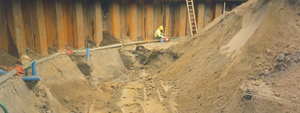
Dry ground conditions are paramount to ensure a safe working environment inside the excavation and ensures construction can continue to take place without delay. If dewatering is overlooked during the planning stage, then the excavation can flood with groundwater and construction must stop until the water is removed and a dewatering system is installed.
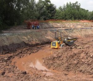
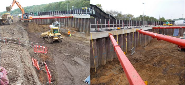
The image below shows what happens when dewatering isn’t planned for. The result is impossible ground conditions to work in. The second photo shows how the ground is improved after a dewatering system is installed.
Dewatering is a temporary works technique that is required throughout the temporary work’s stage until the excavation is made waterproof, at which point the dewatering system can be switched off and decommissioned. Once switched off, the water level will return to its original level.
Dewatering is also required to reduce groundwater pressures on underground structures such as the retaining wall or base slab. In some cases, excavation to formation level can take place in dry soil without dewatering, however, beneath the excavation there may be a more permeable aquifer with a high groundwater head (artesian water pressure). When the ground is excavated, the weight of the soil is removed and the groundwater pressure can cause the soil to fail, causing uplift failure of the ground at the excavation base. This can subsequently result in groundwater flooding of the excavation. Sometimes it is necessary to install a dewatering system to lower groundwater pressures and reduce the risk of uplift failure from occurring.
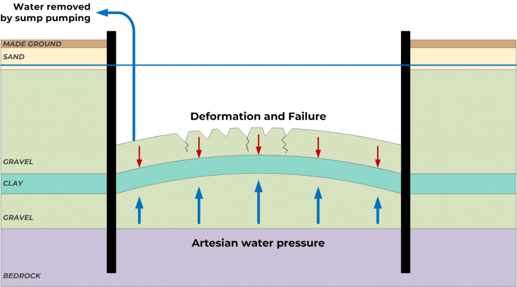
The schematic above shows what can happen due to artesian water pressure in an aquifer below the excavation level. A sump pump is being used to remove any residual water ingress in the excavation, but no dewatering system has been used to lower groundwater pressure.
This results in the failure of the excavation base.
So now that you can identify when a dewatering system is required, what type of systems are there that can solve the groundwater problem.
What methods of dewatering are there?
There are several techniques for undertaking dewatering and controlling groundwater. These can be subdivided into two categories: groundwater cut off methods and dewatering system methods.
Groundwater cut off methods are usually structural methods to cut off water-bearing strata in the ground. For example, sheet pile walls can be installed so they are founded in a low permeability clay layer which cuts off a high permeability sand layer that sits above.
This will prevent large volumes of groundwater flow from flowing into the excavation from the sand layer. Instead, there may be some residual groundwater flow through the clay strata which is easily managed.
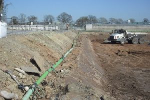
Often dewatering systems are used in conjunction with cut off methods, as shown in the image above. Sometimes it is not feasible to cut off water-bearing strata using a cut off wall, as this would be too costly or physically unachievable. This is when dewatering systems are required.
Dewatering systems typically comprise a combination of wells and pumps. The wells are used to extract water from the aquifer at the target depth. Pumps are then used to pull the water out of the wells and bring it to the surface where it must be disposed of.
There are several different kinds of wells and pumps which can be utilised. The most suitable solution is dependent on the ground conditions and groundwater control requirements.
Dewatering system design is the process of coming up with the best solution for the site conditions to reach the groundwater control requirements.
The following section looks at the different kind of dewatering systems that can be used to manage groundwater on a construction site.
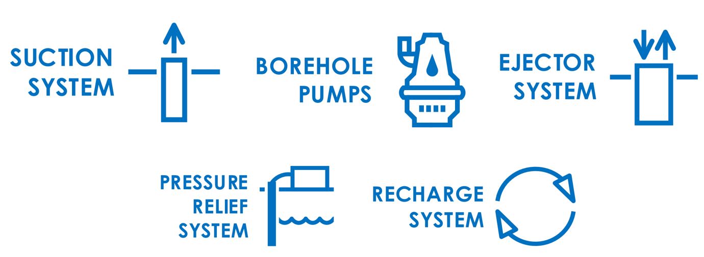
Well Point Suction System
Well point systems comprise of shallow wells which are connected to suction pumps. They offer an economical and effective method of groundwater control when only shallow excavations are required.
They have the advantage of being easy to install in most ground conditions as well as being easy to maintain. They can be used to dewater granular soils, or stratified fine graded soils if the wells are spaced more closely.
Well point systems require a suction pump to be placed at ground level. Suction pumps are capable of lifting groundwater up to 8 metres, so they can’t be used for excavations deeper than this, unless the suction pump can be lowered down into the excavation.
Well points can be installed using either conventional jetting methods, which involve pumping water at high pressure (supplied by a jetting pump and/or compressed air) through a steel placing tube suspended by a 360° excavator, or by drilling augured boreholes and fitting well casing with a granular filter.
Once installed, individual wellpoints are connected to a horizontal vacuum header (collection) main which is connected to the suction pump. If the excavation is large, often multiple suction pumps will be required.
Borehole Pump System
Borehole pump systems comprise an array of drilled wells and borehole submersible pumps. Borehole pumps are placed at the bottom of a well, which means they do not require suction to operate. This enables greater drawdowns to be achieved than with a single stage wellpoint system.
The boreholes tend to be drilled with a larger drilling diameter than wells used for a suction system, typically between 100mm to 350mm diameter. This enables the borehole pump to be fitted inside the well casing. The well casing consists of a plastic pipe of which a section is slotted or perforated to form a well screen to allow water to enter. Over depths where water is not required to be pumped, plain unperforated pipe is fitted. The annulus between the borehole and the well screen casing is backfilled with filter media to form what is known as the filter pack. The filter pack is designed to prevent fines from being extracted with the groundwater. A well-designed filter pack will result in crystal clear water.
The wells are generally placed outside the area of proposed excavation and are usually situated around the full perimeter, as this provides the maximum drawdown effect in the centre of the excavation. Sometimes they are positioned inside the excavation footprint. This may be because there is a partial groundwater cut off and the wells would not be very effective on the outside of the retaining wall.
Wells are typically drilled between 10m and 50m depths but can be deeper on large-scale projects such as shafts and tunnels.
Once installed and pumped each well creates a cone of depression or drawdown around itself, which in a high permeability aquifer may extend for several hundred metres. The interaction between the cone of drawdown from each well produces the drawdown required for excavation over a wide area.
The initial cost of installing a deep well system is significant and is more than for a suction well point system. A high standard of expertise in the design and control of installation procedures is required to ensure that good practices are implemented.
OGI specialise in the design of borehole pump systems. Our focus is on providing an optimised and cost-effective solution for the client.
Ejector Systems
An ejector borehole system is generally used in areas where the soils have a low permeability, such as a silt or silty clay soil. It is especially well suited for deep excavations with stratified soils. The ejectors are installed at relatively close spacing similar to a wellpoint system but can drawdown groundwater up to 30 metres.
In a typical ejector system, a series of ejector wells are installed and connected to two parallel header pipes. One header is a high -pressure supply line and the other header is low pressure return line. Both lines run to a central pump station which feeds water under pressure to ejectors placed at the bottom of the wells.
The system uses a venturi to draw groundwater into the well screen and up to the surface. Water is pumped under high pressure along the annulus between the two pipes and is forced through the nozzle and venturi. The groundwater is then recovered through the well and into the return pipe, resulting in a stabilising effect in fine-grained soils.
The volumes of water which can be pumped by each system are generally low, typically less than 6 m³ per hour. They are typically ore cost effective than borehole pump systems when the ground is stratified and of low permeability. This is because wells are required to be closely spaced to achieve the drawdown requirements.
Pressure Relief Well System
Pressure Relief wells are often used in conjunction with another type of system. Usually, pressure relief wells are installed inside the centre of the excavation and allow groundwater to bleed passively into the excavation. Water is then collected by a sump pump and pumped out of the excavation.
Pressure relief wells are used to prevent uplift failure due to high groundwater pressure beneath the base slab of an excavation. By enabling groundwater to bleed passively, groundwater pressures are lowered in the aquifer beneath, effectively reducing the risk of uplift failure.
Pressure relief wells can have many other applications too. They can be drilled inclined through a retaining wall to enable groundwater pressures to be relieved behind a retaining wall, thus reducing the forces acting on the wall. They can also be drilled inclined from inside a tunnel lining. This can enable groundwater pressures to be lowered outside a tunnel during open excavation at a tunnel face.
Pressure relief wells are typically drilled using a drilling rig. They are usually a smaller diameter drill size than borehole pump or ejector wells. As they are typically passive, they do not require a pump installed inside them, however, another solution will be required to manage the groundwater that enters the excavation via the pressure relief wells.
OGI have 30+ experience of in designing dewatering systems that combine borehole or suction pump systems with pressure relief wells. Have a look at these projects where these techniques were used.
If you would like OGI to design you a dewatering system that uses any one of these techniques, or would just like some advice, then please give us a call.

No Comments